- 您现在的位置:买卖IC网 > Sheet目录1062 > 101-0688 (Rabbit Semiconductor)CARD D/A EXPANSION RN1300
�� �
�
�the� master,� you� will� also� have� to� connect� DCIN,� +5� V,� and� GND� from� connector� J9� on� the�
�Digital� I/O� Card� to� external� power� supplies.�
�On� the� Demonstration� Board,� check� that� the� factory-default� positioning� of� jumpers� is�
�across� pins� 3–5� and� 4–6� of� header� H2.�
�Make� the� following� connections� from� the� Digital� I/O� Card� to� the� Demonstration� Board.�
�IN00� —� S1�
�IN01� —� S2�
�IN02� —� S3�
�IN03� —� S4�
�+K1� —� +5� V�
�GND� —� GND�
�Jumpers:�
�H1:� None�
�H2:� As� shown�
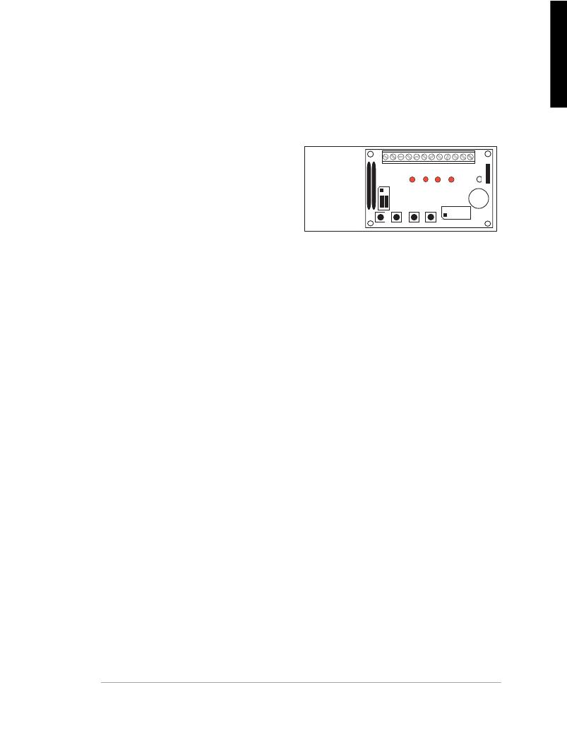
�H2�
�··�
�··�
�··�
�1-2�
�3-4�
�5-6�
�LED1� LED2� LED3� LED4�
�DEMO� BOARD�
�BUZZER�
�Once� this� sample� program� is� compiled� and�
�SW1� SW2� SW3� SW4�
�running,� you� may� press� switches� S1–S4� on�
�the� Demonstration� Board� to� toggle� the� input� low� on� the� corresponding� channel.� Inputs�
�IN04–IN23� can� be� toggled� low� by� touching� the� line� with� a� GND� signal.� The� status� of� the�
�inputs� is� displayed� in� the� Dynamic� C� STDIO� window.�
�?� DIGIN.C� —Demonstrates� the� use� of� the� digital� inputs� by� using� the� Demonstration� Board� to�
�read� individual� input� channels� while� an� individual� channel� is� toggled� from� high� to� low� by�
�pressing� a� pushbutton� switch� on� the� Demonstration� Board.�
�Before� you� run� this� sample� program,� use� the� same� power-supply� connections� and� the� same�
�connections� between� the� Digital� I/O� Card� and� the� Demonstration� Board� as� shown� for� the�
�DIGBANKIN.C� sample� program.�
�Once� DIGIN.C� is� compiled� and� running,� you� may� press� switches� S1–S4� on� the� Demon-�
�stration� Board� to� toggle� the� input� low� on� the� corresponding� channel.� Inputs� IN04–IN23� can�
�be� toggled� low� by� touching� the� line� with� a� GND� signal.� The� status� of� the� inputs� is� displayed�
�in� the� Dynamic� C� STDIO� window.�
�?� DIGBANKOUT.C� —Demonstrates� writing� values� to� a� bank� of� outputs� by� using� the� Demon-�
�stration� Board� whose� LEDs� are� toggled� on/off� via� the� outputs.�
�Before� you� run� this� sample� program,� connect� +K1� and� GND� on� connector� J4� of� the� Digital�
�I/O� Card� to� an� external� +5� V� power� supply.� If� you� are� not� drawing� power� from� the� master,�
�you� will� also� have� to� connect� DCIN,� +5� V,� and� GND� from� connector� J9� on� the� Digital� I/O�
�Card� to� external� power� supplies.�
�Make� the� following� connections� from� the� Digital� I/O� Card� to� the� Demonstration� Board.�
�?� OUT00� —� DS1�
�OUT01� —� DS2�
�OUT02� —� DS3�
�OUT03� —� DS4�
�+K1� —� +5� V�
�GND� —� GND�
�Once� this� sample� program� is� compiled� and� running,� the� Dynamic� C� STDIO� window� will�
�prompt� to� select� an� output� bank.� Select� 1� for� outputs� OUT00–OUT07.� Next� you� will� be�
�prompted� to� enter� a� hex� byte� value—for� example,� enter� AA� to� toggle� LEDs� DS1� and� DS3�
�on/off.�
�User� ’s� Manual�
�31�
�发布紧急采购,3分钟左右您将得到回复。
相关PDF资料
101-0954
KIT DEV RABBIT RCM3360/3370 INTL
101-1050-BE-00025
ADPT USB 2 A FEMALE-2 5PIN .25M
10112627-101LF
MINI-SAS HD 1X2 EXT PCB
10112628-101LF
MINI-SAS HD 1X4 EXT PCB
10136-3000PC
CONN MINI-D 36POS SOLDER PLUG
10136-6000EC
CONN MDR PLUG 36POS IDC GOLD
10150-4CZ3PL
CONN MDR PLUG 50POS VERT T/H
10150-72E2PC
CONN MINI-D 50POS R/A PLUG
相关代理商/技术参数
101-0689
功能描述:开发板和工具包 - 其他处理器 Serial-to-Ethernet
RoHS:否 制造商:Freescale Semiconductor 产品:Development Systems 工具用于评估:P3041 核心:e500mc 接口类型:I2C, SPI, USB 工作电源电压:
101-0690
功能描述:KIT SERIAL-ETHERNET APPLICATION RoHS:否 类别:编程器,开发系统 >> 评估演示板和套件 系列:RabbitCore 3000 产品培训模块:Obsolescence Mitigation Program 标准包装:1 系列:- 主要目的:电源管理,电池充电器 嵌入式:否 已用 IC / 零件:MAX8903A 主要属性:1 芯锂离子电池 次要属性:状态 LED 已供物品:板
101-0691
功能描述:模块化系统 - SOM RCM3300 RABBITCORE
RoHS:否 制造商:Digi International 外观尺寸:ConnectCore 9P 处理器类型:ARM926EJ-S 频率:150 MHz 存储容量:8 MB, 16 MB 存储类型:NOR Flash, SDRAM 接口类型:I2C, SPI, UART 工作电源电压:3.3 V 最大工作温度:+ 85 C 尺寸:1.97 in x 1.97 in x 6.1 in
101-0697
功能描述:单板计算机 BL2102 Bottom Mnt RoHS:否 制造商:Ampro By ADLINK 外观尺寸:EPIC 处理器类型:Intel Atom D510 频率:1.66 GHz 存储容量:2 GB (max) 存储类型:DDR2, L2 Cache 接口类型:Ethernet, PS/2, SATA, Serial, USB 工作电源电压:5 V, 12 V 功耗:13 W 最大工作温度:+ 70 C 尺寸:165.1 mm x 114.3 mm
101-0698
功能描述:模块化系统 - SOM RCM3310 RABBITCORE
RoHS:否 制造商:Digi International 外观尺寸:ConnectCore 9P 处理器类型:ARM926EJ-S 频率:150 MHz 存储容量:8 MB, 16 MB 存储类型:NOR Flash, SDRAM 接口类型:I2C, SPI, UART 工作电源电压:3.3 V 最大工作温度:+ 85 C 尺寸:1.97 in x 1.97 in x 6.1 in
10-106C
制造商:Datak Corporation 功能描述:
10106DC
制造商:Freescale Semiconductor 功能描述:10106DC
10106F
制造商:North American Philips Discrete Products Div 功能描述:Logic Circuit, Dual 3-Input NOR, 16 Pin, Ceramic, DIP